 English
 Español
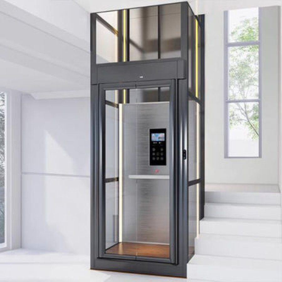
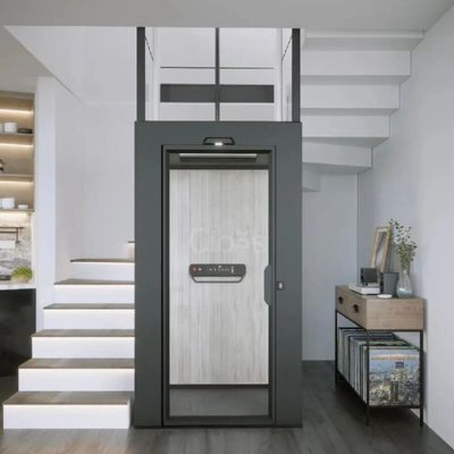
01 · Fit
Is this the right lift for the house?
A compact screw-driven elevator makes sense when the project has a narrow shaft, a long but finite travel, and a power supply that can support a single-phase drive. It is a poor fit when the building needs to move more than 400 kg, when the travel exceeds 50 ft, or when the site cannot provide the structural and electrical conditions the final design requires.
The decision is easier if you separate three questions: what the lift must carry, how far it must travel, and what the building can accept. The answers point to a model, a shaft layout, and a set of site works. They should be settled before anyone orders equipment.
Typical fit
Compact retrofit
An existing house with a tight stairwell or a narrow corner, where a small car is the only realistic option.
Typical fit
Multi-floor home
A house with several levels and a total travel within 50 ft, where a slow single-phase lift is acceptable.
Typical fit
Indoor or outdoor
A project that can protect the equipment from weather and provide a level landing at every stop.
When this model is the wrong choice
- Travel above 50 ft. The page limit is 50 ft (15.24 m). A taller run needs a different model or a different layout, not a longer rail cut on site.
- Rated load above 400 kg. If the actual load case includes heavy equipment, a large wheelchair, or several passengers, move to a higher-capacity model and check the car size as well as the number.
- High traffic or frequent goods handling. A 0.15 m/s residential lift is not a passenger elevator for an office, a shop, or a busy rental property.
- No single-phase supply. The published supply is 220 V, 50 Hz, single phase. A three-phase-only site needs an electrical solution confirmed by the supplier and the local electrician.
- No space for the car, door, and structure. “Compact” is relative. The car, door operator, guide rails, and landing sills still consume space; the approval drawing decides whether they fit.
Three-question fit check
This is a first-pass screen, not a design. It uses only the published limits on this page.
What “400 kg” actually covers
400 kg is the rated load on this page, not a target to fill to the last kilogram. The useful load is the passenger or goods weight plus anything carried into the car, and it has to be read together with the car floor area and the door opening. For a private house, the practical question is “what is the heaviest realistic trip?” If the answer includes a mobility scooter, a bulky wheelchair, or building materials, write that load down and check it against 400 kg before selecting the model.
“Compact” describes the package relative to the travel and load, not a promise that it will fit any stairwell. Ask for a plan view with the car, door, rails, drive column, and maintenance clearances. If the drawing does not show those items, the compact claim cannot be checked.
Use the page values, then stop
This page states 400 kg, 50 ft, 0.15 m/s, automatic sliding doors, microprocessor control, 220 V single-phase, indoor or outdoor installation, emergency stop, safety sensors, door interlocks, CE, ISO 9001, and a one-year warranty. It does not state cabin dimensions, shaft dimensions, pit depth, overhead height, door opening, or stop count. Those are design inputs, not assumptions to fill in from a catalogue photo.
02 · Drive and anti-drop
How a screw drive holds a car, and what “anti-drop” should mean
A screw-driven lift turns a rotating screw column. A nut fixed to the car travels up and down that column. Because the nut is captive on the screw, the car cannot simply fall free while the nut and screw remain engaged. That is the mechanical basis for the “anti-sudden-drop” language used on this page.
The holding force depends on the thread form, the nut material, the lubrication, the load distribution, and the condition of the nut. A screw drive is not a licence to skip a holding brake, a secondary load path if fitted, overspeed protection, or a periodic inspection.
Self-locking is a property, not a complete safety system
A screw thread can be self-locking when its lead angle is low enough that friction prevents the load from driving the screw backwards. That is useful, but it is not the same as a certified safety device. The holding brake, a secondary load path if fitted, the overspeed detection, and the door interlocks each cover a different failure mode. A supplier who says “it cannot fall” without explaining those layers is giving you a slogan, not an engineering answer.
Ask for the load path in writing: which component carries the car, what the secondary nut contacts, and how the assembly is inspected. If the answer is only a brochure phrase, keep asking.
In practice, the screw drive removes rope traction from the load path. It does not remove the holding brake, a secondary load path if fitted, the door interlocks, the landing detection, or the need to inspect the nut and keep the screw clean. Those items remain part of the safety case and the maintenance plan.
How to test the anti-drop claim
You cannot prove a safety function by watching a car sit still. Ask for a test procedure and a record. A useful sequence covers the brake, any secondary load path, the overspeed device, and the door circuit separately. Load the car to its rated load for the brake test, and repeat the test after installation, not just at the factory.
- Holding brake test. Stop the car at a landing with rated load, remove drive power, and confirm the car holds without visible creep.
- Secondary load path check. Ask whether a safety nut is fitted. If it is, confirm installation, gap, and the commissioning record.
- Overspeed test. Use the manufacturer’s test method; do not improvise a drop test on a customer’s lift.
- Door circuit test. Open the door at a landing and try to start the car; the car must not move. Try to open the door while the car is between floors; the door must remain locked.
- Emergency stop test. Press the stop button during travel and confirm the car stops and remains stopped until reset.
“Anti-sudden-drop” is not a certificate
The phrase describes a design intent. It does not replace the CE marking, the ISO 9001 quality system, or the local inspection regime. Ask for the certificate numbers, the standards they cover, and the name of the body that issued them. If the documents do not match the model, the claim is not verified.
Sources used in this section: the page’s specification panel (screw-driven drive, emergency stop, safety sensors, door interlocks, CE, ISO 9001, one-year warranty) and the page’s published description of the anti-sudden-drop design. The general explanation of screw-nut load paths is engineering background, not a model-specific test result.
03 · Specifications
The numbers that decide the layout
The specification panel is the authority for this page. The table below repeats the published values and adds what each one means on site. It does not invent cabin or shaft dimensions; those are not published here.

| Parameter | Published value | What it means on site |
|---|---|---|
| Rated load | 400 kg / 882 lb | The maximum load the car is rated to carry. Check the real load case, including wheelchair, attendant, and goods. |
| Travel | Up to 50 ft / 15.24 m | Measure between finished floor levels, not between structural slabs. The highest and lowest stops set the travel. |
| Speed | 0.15 m/s / 29.5 ft/min | A low residential speed. A full 15.24 m run takes about 102 seconds at constant speed, before acceleration and door time. |
| Drive | Screw-driven | The car is moved by a nut on a screw column. The shaft must be straight and the screw protected from dirt and water. |
| Door type | Automatic sliding doors | The landing and car door layout needs clear space for the slide and the operator. Door width is not published; confirm it on the drawing. |
| Control | Microprocessor-based | The controller manages travel, levelling, door logic, and fault codes. Ask for the fault list and the reset procedure. |
| Power | 220 V, 50 Hz, single phase | Confirm the supply at the final position, including cable size, breaker, earth, and isolation. A three-phase site needs a supplier-approved solution. |
| Installation | Indoor or outdoor | Outdoor installation needs weather protection, drainage, and a finish suitable for the local climate. “Outdoor” is not a licence to leave the equipment exposed. |
| Safety | Emergency stop, safety sensors, door interlocks | These are the published devices. Test each one at commissioning and record the result. |
| Certification | CE, ISO 9001 | Ask for the certificate scope and number. A CE mark on a component is not the same as a CE mark on the complete lift. |
| Warranty | 1 year | Confirm what the warranty covers, what voids it, and who performs the work in the destination country. |
Unit conversions are arithmetic: 50 ft × 0.3048 = 15.24 m; 400 kg × 2.20462 = 881.8 lb; 0.15 m/s × 196.85 = 29.53 ft/min. The page’s original values remain the specification.
What the table does not tell you
Five dimensions decide whether the lift can be built, and none of them appear in the published specification panel. They are the car’s internal size, the shaft or enclosure size, the pit depth, the overhead clearance, and the door opening. A sixth item, the number of stops, is also missing. Do not let a sales drawing fill those gaps with assumptions.
| Missing input | Why it matters | Who should provide it |
|---|---|---|
| Cabin and shaft size | Sets the usable floor area, the structural opening, and the clearances for rails, screw, and doors. | Supplier drawing plus architect’s survey. |
| Pit and overhead | Affect the lower landing, the buffer space, the drive enclosure, and the upper safety space. | Supplier drawing and site measurement. |
| Door opening | Controls access for wheelchairs and furniture; also sets the landing finish detail. | Client requirement and supplier door schedule. |
| Stop count | Each stop adds a landing door, a sill, a call station, and a set of interlocks. | Architect’s floor plans. |
Speed in plain terms
At 0.15 m/s, the car covers one metre in about 6.7 seconds. A 3 m rise takes roughly 20 seconds, plus acceleration, levelling, and door time. That is normal for a private lift; if the household expects passenger-elevator speed, this is the wrong product category.
Three-way unit converter
Convert the three figures buyers check most often. The output is arithmetic, not a new specification.
= 50.00 ft
= 881.8 lb
= 29.5 ft/min
Conversions: 1 m = 3.28084 ft; 1 kg = 2.20462 lb; 1 m/s = 196.85 ft/min. The page’s published values remain the specification.
04 · Travel
What 50 ft of travel demands from the building
Fifty feet is a long way for a residential screw lift. It is also a limit, not a target. The real travel is the vertical distance between the lowest and highest finished floor levels. If the architect’s section shows 15.24 m between those levels, the lift is at the top of its published range. If the section shows more, the project needs a different model.
Long travel changes more than the rail length. It changes the number of rail joints, the fixing pattern, the straightness tolerance, the cable and travelling cable arrangement, the door count, and the time the car spends in motion. Each of those items has to be resolved before the shaft is built.
Measure the right thing
Site measurements taken to a structural slab are not the same as finished floor levels. Tiles, screed, underfloor heating, and thresholds can shift the landing height by tens of millimetres. On a long run, those small differences accumulate into a car that does not line up with the landing. Use the architect’s finished floor levels and confirm them on site before fabrication.
Write down four levels at every stop. The supplier needs all four to set the sills and rail brackets:
- Finished floor level.
- Structural slab level.
- Door threshold level.
- Clear headroom above the landing.
If any level is missing, the drawing is not ready.
Travel planner
Arithmetic only. It compares a simple floor-to-floor total with the 50 ft limit; it does not replace the approval drawing.
Guide rails: straightness is the whole job
A screw lift does not pull the car along a rope. The car is guided by rails, and the nut follows the screw. If the rails are out of plumb, the car will rub, the door will bind, and the nut will carry loads it was not designed for. The rail installation is therefore not a secondary task to be rushed after the car arrives.
Rails should be continuous where the design calls for continuity, with joints staggered so that no two joints sit at the same bracket. Brackets need a structural substrate: a structural wall, a steel frame, or a purpose-made shaft. The fixing pattern, anchor type, and bracket spacing belong on the approved drawing.
Checks before the rails go in
- Shaft is plumb within the tolerance on the drawing.
- Bracket substrates are structural and accessible.
- Rail joints are staggered and aligned.
- Anchor type matches the substrate, not the installer’s habit.
- Screw column is vertical and protected from site dust.
Checks after the car is hung
- Car runs without rubbing or abnormal noise.
- Guide shoes are adjusted evenly.
- Door sill lines up at every landing.
- Rail bolts are torque-marked and recorded.
- No temporary spacers or packing remain.
Overhead, pit, and the space nobody photographs
The overhead is the space above the top landing; the pit is the space below the lowest landing. Neither dimension is published on this page. A builder who budgets “about a metre” for each is guessing. The approved drawing must give the figures, and the site must be measured against them before the floor is poured or the opening is cut. If the project has no pit, do not assume this model can be installed pitless; ask for a pitless or low-profile variant and get the structural detail in writing.
Water is the hidden issue
A pit is a sump. If the site drains toward the shaft, water will collect under the car. Specify a sump, a drain, or a sealed tank as appropriate, and check the detail before the concrete is placed. Outdoors, the pit detail matters even more because rain can enter at the landing threshold.
The lift also adds dead and dynamic load to the building. The approval drawing should show the reactions at the rail brackets and the machine support. If the building is timber-framed or has a lightweight steel mezzanine, ask a structural engineer to check those reactions before fabrication; a long rail run on a flexible wall will amplify vibration.
The 50 ft limit is measured, not estimated
Do not accept a travel figure taken from a brochure photograph or a floor-plan scale. Measure the finished floor levels and put them on a section drawing. If the total is within 15.24 m, the model is eligible. If it is not, stop and change the design.
05 · Power and doors
Backup power, door interlocks, and what happens when the supply fails
The page lists backup power in its published description, but it does not state the backup type, the number of trips it can make, or whether it lowers the car to a landing. Those details change the value of the feature. A battery that only lights the alarm is not the same as a battery that drives the car to the nearest floor and opens the door.
Before you accept the feature, ask for a functional description and a test record. What does the backup actually operate? How long is the switch-over? How many full trips can it make at rated load? What happens when the battery is flat, and how is it tested without taking the car out of service?
There are three common meanings: the backup keeps the alarm or phone dialer alive; it drives the car to the nearest landing and opens the door; or it supports a manual emergency lowering procedure. The first is not a rescue, the second is what most buyers expect, and the third depends on a trained person on site. Find out which one is supplied.
Test the backup under load
A no-load test in the factory proves very little. The test that matters is done on site, with the rated load in the car, with the normal supply isolated, and with the landing doors closed. Record the time to switch over, the landing the car reaches, the door opening time, and the battery voltage before and after. Repeat the test at least once after the battery has been in service for a few months.
- Confirm the battery and charger are healthy, then load the car to its rated load.
- Isolate the normal supply at the dedicated isolator, not at the main breaker.
- Record the switch-over time, the landing reached, the door operation, and the battery voltage.
- Restore the supply and confirm the charger returns to normal.
Door interlocks are a sequence, not a switch
A door interlock proves the door is closed and locked before the car can move, and proves the car is at the landing before the door can open. A magnet glued to a reed switch is not an interlock; the device should be mechanically actuated by the door lock and monitored by the controller.
Test the sequence at every landing. Open the door and press the call button; the car must not move. Send the car away and try the landing door; it must stay locked. Record the results landing by landing.
| Device | Purpose | Commissioning test |
|---|---|---|
| Emergency stop | Stops the car and holds it stopped until reset. | Press during travel at a safe point; confirm stop, alarm, and reset procedure. |
| Safety sensors | Monitor the zone defined by the supplier; commonly the door path. Confirm the monitored zone first. | Interrupt the protected zone with a test piece; confirm the specified response. |
| Door interlocks | Prevent movement with a door open and prevent opening away from a landing. | Test every landing door and the car door separately. |
| Backup power | Keep alarm or car operation alive during a supply failure, as specified. | Isolate supply with rated load; record function, time, and battery condition. |
| Phone dialer (optional) | Call a programmed number from the car. | Call the number, confirm two-way speech, and check the stored number. |
Power and door readiness checklist
Tick what is already confirmed. Anything left unticked is a question for the supplier or the electrician.
0 of 8 confirmed
Do not test the safety circuit by shorting it
Bypassing an interlock to “make it run” defeats the device and can leave the lift in an unsafe state. If a door circuit faults, diagnose it with the controller’s fault code and the wiring diagram. A temporary bypass must be controlled, logged, and removed before the lift is handed over.
06 · Indoor and outdoor
Indoor and outdoor are different projects
The page says the lift can be installed indoors or outdoors. That is a useful range, but it does not mean the same package suits both. An indoor lift sits in a controlled environment. An outdoor lift faces rain, sun, wind, dust, leaves, insects, and temperature swings. The enclosure, finish, drainage, and maintenance plan have to change with the exposure.
| Item | Indoor installation | Outdoor installation |
|---|---|---|
| Enclosure | Shaft or hoistway within the building envelope; fire and acoustic separation may apply. | Weather-resistant enclosure or structural glazing; roof and canopy detail matter. |
| Finish | Interior-grade paint, laminate, stainless, or glass according to the cabin specification. | UV-stable coating or a stainless grade chosen for the site; coastal sites need a higher grade. |
| Water | Keep the pit dry; deal with cleaning water and condensation. | Positive drainage, threshold upstand, sealed penetrations, and a sump or drain. |
| Wind | Not a direct load on the car, but the shaft must be stable. | The enclosure and rails must resist local wind load; check the structural design. |
| Temperature | Normally stable; avoid direct heat sources and freezing drafts. | Specify the operating temperature range and protect the controller and battery. |
| Maintenance | Normal housekeeping; keep the pit and door tracks clean. | More frequent inspection of seals, drains, fasteners, and the screw column. |
What to specify for an outdoor site
Start with the exposure. Is the lift under a roof, against a wall, or fully exposed? Does the site get driving rain, salt air, snow, or strong sun? The answers determine the enclosure finish, the stainless grade, the sealant, and the maintenance frequency. “Outdoor” on a specification sheet is a category, not a material guarantee.
- Roof and canopy. Keep direct rain off the landing and the controller. A canopy that drains onto the landing is worse than no canopy.
- Threshold. Raise the landing threshold above the external paving and slope the paving away from the door.
- Drainage. Provide a sump or drain at the pit. Check that it cannot back up in a storm.
- Fasteners and seals. Use stainless or coated fixings, specify UV-stable seals, and set a replacement interval.
- Controller, battery, and vegetation. Keep the controls dry and ventilated, and keep leaves and insects out of the pit and door track.
Indoors, the common failures are dust, cleaning water, and heat. Keep the pit sump working, do not store paint or cement in the shaft, and give the controller a ventilated position. Protect the door track during the rest of the building works and clean it before commissioning.
One question that saves a lot of money
Ask what changes in the bill of materials for an outdoor installation at this site. If the answer is only “a different paint colour”, the outdoor package has not been engineered.
07 · Safety and acceptance
What to inspect before the lift is handed over
A residential lift is a small machine, but it still has to be accepted properly. The handover should produce a signed checklist, a set of drawings, a controller fault list, a maintenance schedule, and the certificate documents. A verbal “it’s fine” is not an acceptance record.
The page lists emergency stop, safety sensors, and door interlocks, and states CE and ISO 9001. Those are the published claims. The acceptance process should prove the devices work on this installation and confirm that the documents match the model supplied.
Certification: what CE and ISO 9001 do and do not tell you
CE marking indicates that the product is placed on the market in conformity with the applicable European legislation, as declared by the manufacturer. ISO 9001 is a quality management system standard; it says the supplier has a documented process, not that every lift is identical. Neither document replaces the local building approval, the electrical inspection, or the commissioning test.
Ask for the certificate numbers, the issuing body, the product scope, and the date. Check that the model and the drive type on the certificate match the equipment on site. If the certificate covers a component rather than the complete lift, say so in the handover file. That is not a reason to reject the lift; it is a reason to describe the compliance accurately.
Ten-point acceptance checklist
Use this at handover. Each item should have a result, a date, and a signature.
0 of 10 complete
What “levelling” should feel like
At every landing, the car floor and the landing floor should line up within the tolerance stated in the commissioning document. A small step is a trip hazard, and it also points to a landing-detection or rail-alignment problem. Test with the rated load and without it, because the car can sit at a different height when loaded.
Listen during the run. A screw lift is not silent, but it should not bang, scrape, or squeal. A rhythmic click at a rail joint can be normal; a metallic scrape is not. Record the noise and vibration at each landing so that a later change can be compared with the baseline.
Documents to keep
- Approved layout and section drawings, signed by supplier and client.
- Electrical diagram and dedicated circuit details.
- Commissioning record, fault code list, and reset instructions.
- Warranty terms, certificate copies, and the service contact.
- Maintenance schedule and spare-parts list.
Do not sign until the test record is complete
It is common for a handover to happen while the building is still finishing. If the final floor levels, power supply, or drainage are not complete, sign only a partial handover with the outstanding items listed. A final acceptance signature should mean the lift, the site, and the documents are all ready.
08 · Installation
The installation sequence, and what has to be ready first
A screw lift is not difficult to install when the shaft, the power, and the access are ready. It becomes expensive when those items are discovered late. The sequence below is the order that avoids rework. The exact method belongs to the installer; the sequence is what the client and the main contractor need to plan around.
Step 1
Survey and approval drawing
Measure the finished floor levels, shaft, openings, headroom, pit, and power. Produce a signed layout and section before fabrication.
Step 2
Structural and site works
Build the shaft or enclosure, prepare the pit and drainage, form the openings, and provide the rail substrates.
Step 3
Power and lighting
Install the dedicated 220 V single-phase circuit, isolator, earth, and working lights. Protect the supply until commissioning.
Step 4
Delivery and protection
Confirm access, lifting equipment, and a dry store. Keep the screw column and controller protected from dust and water.
Step 5
Rails and screw column
Set the rails plumb, fix the brackets to the approved substrate, align the joints, and install the screw column.
Step 6
Car, doors, and wiring
Install the car, door operator, landing doors, sills, call stations, and travelling cables. Check clearances before power-up.
Step 7
Test and commission
Run the acceptance tests, set the levelling, record the fault codes, and demonstrate the emergency procedures.
Step 8
Handover and training
Hand over drawings, certificates, warranty terms, and the maintenance schedule. Train the household on the controls and the alarm.
What the client has to provide
- Clear access for the largest component, including the car and the screw column.
- A dry, secure store for equipment before installation.
- Working power and lighting for the installation team.
- A level landing at every stop, with the final floor finish agreed.
- A pit that is clean, dry, and drained, with the specified sump or drain.
- Structural openings and rail substrates built to the approved drawing.
- A safe working area, with edge protection and barriers as required.
- A named person who can approve changes and sign the handover.
What the supplier has to provide
- Approved layout, section, and wiring drawings before fabrication.
- A packing list and a delivery schedule that matches the site programme.
- Installation method, torque values, and the rail-fixing pattern.
- Commissioning records and the controller fault list.
- Certificate copies with numbers and scope.
- Warranty terms and a named service contact in the destination country.
- A spare-parts list with lead times for wear items.
Why installations slip
Most delays come from the building, not the lift: a narrow opening, a floor level that moves after approval, power on the wrong phase, a wet pit, or a finish change after the panels are cut. Freeze the drawing before fabrication and keep a change log. Inspect the site before the order, before delivery, and before commissioning.
Production time is not installation time
The specification panel states the production lead time. That is the time to manufacture and prepare the shipment, not the time to install. Shipping, customs, site access, building works, and commissioning add their own duration. Plan the lift as part of the construction programme, not as an appliance that arrives and plugs in.
09 · Maintenance
Maintenance that actually protects a screw lift
The published warranty is one year. A warranty is not a maintenance plan. The screw, nut, rails, doors, and battery need inspection from the first year onward, and the inspection record is what tells you whether the lift is ageing normally or wearing out.
Agree a written schedule with the supplier before handover. The intervals depend on use, environment, and local rules. The list below is the minimum scope to discuss; it is not a substitute for the manufacturer’s manual.
| Item | What to check | Why it matters |
|---|---|---|
| Screw and nut | Lubrication, wear, backlash, foreign material, corrosion. | The nut is the primary load path; wear changes the car’s behaviour. |
| Secondary nut (if fitted) | Ask whether fitted; if so, check gap, contact marks, adjustment, and mounting. | It is the secondary load path if the main nut degrades. |
| Guide rails | Bolt torque, bracket condition, joint alignment, lubrication if specified. | Loose rails cause rubbing, noise, and door misalignment. |
| Doors | Track, rollers, sill, interlock, sensor, closing force. | Doors are the most-used part and the most common source of faults. |
| Controller | Fault log, terminal tightness, dust, cooling, backup battery. | A clean controller with a reviewed fault log prevents repeat outages. |
| Emergency system | Alarm, phone dialer, emergency stop, manual release, backup power. | These systems are only useful if they work when the power fails. |
| Pit and drainage | Water, debris, sump, pump, odour, corrosion. | Water destroys bearings, switches, and the screw over time. |
Lubrication: follow the manual, not the hardware store
The screw and nut are a matched pair. The wrong lubricant can attract dust, harden, or attack the nut material. Use the lubricant specified by the manufacturer, apply the specified quantity, and record the date. Do not mix brands or “top up” with a different grease. If the site is dusty or outdoors, the inspection interval may need to be shorter, not the lubricant quantity larger.
What a service visit should produce
- A dated checklist with measured values, not just “OK”.
- Photos of the nut, screw, rails, and door track.
- The controller fault log, with new codes explained.
- Parts replaced, items needing attention, and a signed copy for the household.
Warranty questions to settle before you buy
The page states a one-year warranty. That is the headline. The value depends on the details: which parts are covered, whether labour and travel are included, whether the warranty is honoured in the destination country, and what the exclusions are. Ask for the written terms, not a sentence in a quotation.
- Does the warranty cover the screw, nut, controller, doors, and battery separately?
- Is labour included, and who pays for travel to a remote site?
- What maintenance records are required to keep the warranty valid?
- Is there a local service partner, and what is the response time?
Do not let the lift become “someone else’s problem”
When the builder, electrician, and supplier leave, the household is left with the asset. Keep one file with the drawings, certificates, test records, and service history. A lift without records is difficult to service.
10 · Questions
Questions buyers ask before choosing this model
The answers below use the published values on this page and identify the items that must come from the approved drawing. Where the page is silent, the answer says so.
How far is 50 ft in metres, and how long does the trip take?
50 ft is 15.24 m. At the published speed of 0.15 m/s, a full 15.24 m run takes about 102 seconds at constant speed, before acceleration, levelling, and door time. A shorter run takes proportionally less time. The car is designed for residential use, not for rapid passenger transport.
Is 400 kg enough for a wheelchair and an attendant?
400 kg is the rated load. Whether it is enough depends on the combined weight of the wheelchair, the user, the attendant, and anything carried. Add those figures and compare them with 400 kg. Also check the car floor area and the door opening, because a wheelchair can be within the weight limit but still not fit through the door. The page does not publish the car or door dimensions.
Does this lift need a pit?
The page does not state a pit depth, and it does not claim that the model is pitless. Treat the pit as a design item to be confirmed on the approval drawing. If the site has no pit, ask the supplier for a pitless or low-profile variant and get the structural detail in writing. Do not excavate or omit a pit based on a brochure assumption.
Can it be installed outdoors?
The published installation range is indoor or outdoor. An outdoor installation needs a weather-resistant enclosure, suitable finish and fasteners, a raised threshold, drainage, and protection for the controller and battery. The category “outdoor” does not by itself define the enclosure or the corrosion grade. Specify those items for the site.
What happens during a power failure?
The page’s description lists backup power, but it does not state whether the backup lowers the car to a landing, keeps the alarm alive, or supports another function. Ask for the functional description, the number of trips it can make at rated load, and the battery test procedure. Test it on site, not just in the factory.
What does “anti-sudden-drop” mean in practice?
It refers to the screw-and-nut load path: the car is carried by a nut on a screw column, so it does not rely on rope traction. A complete safety case still needs a holding brake, a secondary load path if fitted, overspeed protection, and door interlocks. Ask for the load path, any secondary-nut arrangement, and the commissioning tests. A slogan is not a test record.
What do CE and ISO 9001 cover?
CE marking is a declaration that the product conforms to the applicable European legislation within its stated scope. ISO 9001 is a quality management system standard. Neither replaces local building approval, electrical inspection, or commissioning. Ask for the certificate numbers, issuing body, scope, and date, and check that they match the model supplied.
How many stops can it serve?
The page does not publish a stop limit. The number of stops affects the travel, the number of landing doors, the call stations, the interlocks, and the controller configuration. Give the architect’s floor plans to the supplier and ask for a stop-by-stop layout. Do not infer the limit from the 50 ft travel alone.
How noisy is it?
The page does not publish a sound pressure level, so no dB figure should be quoted. A screw drive has a different sound character from a rope lift; motor, rail, and door noise all contribute. Ask for a measured test if noise is critical, and specify the measurement position and standard. Do not accept “whisper-quiet” without a number.
What do I need to send for an accurate quotation?
Send the floor plans, a section, finished floor levels, total travel, stop count, required load, available power, indoor or outdoor location, car finish, door width, destination country, and any local code. Without them, the quotation is only a budget indication.
11 · Quote
What to send, and what the quotation should contain
A useful quotation is a design document, not a price on a postcard. It should state the model, the duty, the car and shaft dimensions, the pit and overhead, the door arrangement, the finish, the safety devices, the certification, the warranty, the lead time, the packing, and the scope of installation. If any of those items is missing, the price is not comparable with another supplier’s price.
Ten-item request checklist
Tick each item when it is ready to send. The more complete the pack, the fewer assumptions end up in the price.
0 of 10 ready
What the quotation should state
Technical
- Model, drive type, rated load, and speed.
- Car dimensions, door opening, and finishes.
- Shaft, pit, overhead, stop count, and landing doors.
- Safety devices, controller model, and power requirements.
Commercial and delivery
- Scope of supply and installation, clearly separated.
- Packing, shipping terms, delivery point, and lead time.
- Warranty, exclusions, certificates, and service contact.
- Payment terms and quotation validity.
Questions that expose a weak quotation
Ask what is excluded, who is responsible for the shaft, pit, power, hoisting, and final inspection, and what happens if the site dimensions differ from the drawing. A supplier who can answer those questions has a process.
Send the drawings, not just the dimensions
A section drawing and a plan view remove most of the ambiguity. Include the finished floor levels, the proposed shaft, the power position, and photos of the access route. With those, the supplier can confirm whether the 400 kg, 50 ft model fits the project and what the approval drawing needs to show.
Request a project reviewSpecification source: the product specification panel on this page. General engineering explanations are provided for selection and site planning; they are not a substitute for the approved drawing, the manufacturer’s manual, or the local inspection authority. Items marked as requiring confirmation must be confirmed in writing before fabrication.