 English
 Español
Categories
Contacts
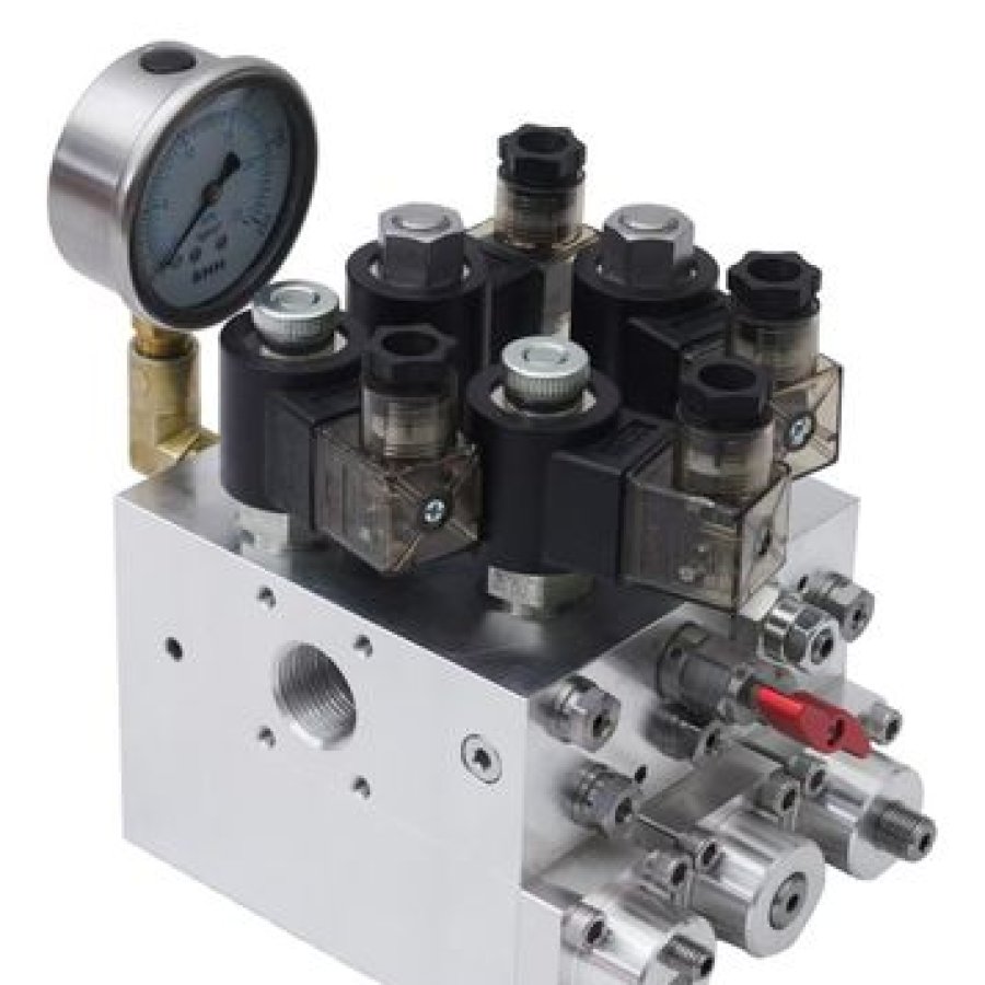
Hydraulic Valve Block for Elevator Pump Stations
Product Details:
Brand Name
YST
Model Number
YSTV-001
Certification
CE, ISO
Place of Origin
China
Payment & Shipping Terms:
Minimum Order Quantity
1
Price
USD 300-600/set
Payment Terms
LC TT
Supply Ability
1,000/month
Delivery Time
10 days
Packaging Details
Export non-fumigation
Product Description
YSTV-001 · elevator pump-station valve block · CE, ISO · integrated flow, pressure and direction control
A hydraulic valve block is useful only when its interfaces are known.
This hydraulic valve block for elevator pump stations is the YSTV-001 unit. It brings solenoid directional valves, pressure regulation, relief functions and a pressure gauge into one housing. A manual shut-off valve gives a technician a defined way to isolate or depressurise the circuit during service. The intended setting is a residential lift or another small hydraulic lifting circuit that needs controlled flow and pressure without a loose collection of separate components.
The page gives the commercial frame and the control concept. It does not publish port sizes, a pressure rating, flow capacity, material grade, coil voltage or a list of approved pump units. Those are not omissions to fill with estimates. They are the project data that determines whether a particular block can be fitted, adjusted and maintained safely.
Suppliers may list the same component as an elevator hydraulic valve or a pump station hydraulic valve. Use the drawing and configuration as the identifier. A familiar name does not make two blocks interchangeable.
Three answers that determine the next document
This is a component enquiry, so a few lines of chat are rarely enough. The useful starting point is the pump-station arrangement with the cylinder, pump, reservoir, block, control connection and service access already marked. Use the three questions below to see which part of the review is still open. The result is guidance on what to prepare, not an automatic product selection.
1Is the application a residential lift, platform lift, accessibility ramp or another compact vertical-transport circuit?
2Can your engineer provide a pump-unit drawing plus the operating duty for review?
3Do you also need to verify the CE/ISO evidence relevant to this supply?
The enquiry has enough structure for a technical review
An engineer can compare the block layout with the pump-station drawing and return a configuration-specific quotation. Keep the drawing, duty, electrical scheme and document request together so the answer is not split between several email threads.
Freeze the missing input before asking for a price
A block can be priced against the correct configuration only after the interfaces and operating duty are visible. If the application is broader than a compact circuit, the review may need a different block or a complete valve assembly. Contact our engineers with what is known and what remains open.
Start with the circuit, not the photograph
The product photograph helps identify the component. The pump-station drawing shows whether the ports, function paths and service access agree. The checklist later on this page lists the evidence worth sending in the first round.
What a hydraulic valve block controls inside an elevator pump station
The block is a junction for three related decisions. It directs hydraulic oil along the required route, it regulates pressure in the working circuit, and it provides an arranged path for flow returning to the reservoir. These functions are interdependent. A block that directs flow correctly but cannot be adjusted within the pump's operating envelope is not a successful match.
In a compact elevator system, the pump supplies hydraulic energy, the cylinder converts that energy into movement, and the reservoir receives returning oil. The valve block sits between those parts. Its layout tells the installer where the pressure, return and working lines connect. Its internal passages and valve positions determine which line is open in each operating state. Its adjustment points allow commissioning within the agreed design limits.
The three states below explain the relationship at a system level. Press the Lift, Hold or Lower button to change the highlighted route. The diagram is educational. It is not a hydraulic schematic for a particular building and it does not replace the approved circuit drawing.
Pump flow is directed toward the lifting circuit. The pressure and relief arrangement, not the color of this diagram, determines the safe operating condition.
Flow
Flow relates to how much oil moves through the circuit in a given time. The block must route that flow without creating an unintended restriction or a path that the pump cannot support. A replacement review therefore starts with the pump and cylinder arrangement, not with the outside shape of the old block.
Pressure
Pressure regulation protects the intended working condition and gives the commissioning technician a controlled reference. The page includes a gauge and relief function in the integrated design. It does not publish a pressure rating, so the project engineer must confirm the setting and the safe upper limit for the complete circuit.
Direction
Directional control decides which line receives flow and which line returns oil. The response of the car depends on the complete valve arrangement, control logic and safety devices. A three-state illustration can explain the concept; it cannot certify that a replacement block will reproduce the original sequence.
Why an integrated block can simplify a compact station
Separate directional valves, pressure controls and relief components require more connections, more mounting points and more places for a technician to trace during service. Integrating those functions inside one housing can make the hydraulic circuit easier to identify and may reduce the number of external joints. That is the practical value described on this page. It is not a promise that every station will become simpler after a block change.
The benefit depends on access. A compact block can be difficult to work on if the pump unit is buried behind a panel or if the gauge faces a wall. The service position belongs in the layout. Leave room to read the gauge, reach the manual shut-off valve, inspect the solenoid covers, disconnect a connector and place a tray beneath the ports without forcing the technician into an unsafe posture.
What the diagram does not tell you
The highlighted line shows a general relationship between pump, block, cylinder and reservoir. It does not show the valve's exact centre condition, pilot arrangement, relief setting, coil logic or method of holding the load. Those details belong to the manufacturer's drawing and the approved elevator design. Use the illustration to ask better questions. Do not use it as a construction schematic.
Engineering boundary: the complete hydraulic system, including load holding and descent control, must be reviewed by the responsible elevator engineer. This page uses a simplified path to explain the block's role and does not approve a valve schedule or safety setting.
What the integrated valve block does
The current product description identifies five design features: an integrated hydraulic control system, precision pressure monitoring, industrial-grade solenoid valves with inspection covers, a manual safety override, and a housing made from hardened, non-corrosive alloys. Each feature answers a practical question for a pump-station builder, but each also needs confirmation at the model level.
Integrated control housing
Solenoid directional control, pressure regulation and relief mechanisms share a single housing. Fewer external connections can reduce the number of leak points and make the hydraulic layout easier to identify. The benefit still depends on correct port mapping and clean assembly.
Pressure gauge
The embedded gauge gives a visible pressure reference during setup and service. It helps a technician compare the observed condition with the approved commissioning value. It does not replace a calibrated test instrument when the project requires measured evidence.
Service-friendly valves
Transparent inspection covers and reinforced oil-port connections are intended to support routine diagnostics and continuous duty in compact equipment. Inspect the covers for leakage or contamination during maintenance and use the approved coil and connector specification.
Manual override
A manual shut-off valve allows the technician to isolate or depressurise part of the system during service. It must be used as part of a written isolation procedure. Closing one valve does not prove that every stored pressure path has been removed.
Housing and fluid compatibility
The page says the block is constructed from hardened, non-corrosive alloys. That is a design statement, not a material certificate. For a project with a specified hydraulic fluid, an outdoor environment, wash-down exposure or a corrosive atmosphere, request the actual housing and seal materials and compare them with the fluid supplier's recommendations. Two blocks can look similar and behave differently after long exposure.
Fluid cleanliness also matters. A valve block contains narrow passages and moving internal parts. Contamination that would pass through a large pipe can still interfere with a solenoid seat or an adjustment element. The maintenance plan should cover the reservoir, filter and filling method as a system, not the block alone. Use clean containers, the approved fluid and the pump-station manufacturer's flushing procedure.
Feature-to-evidence review
The table separates what this page states from what a buyer should receive before approving a project-specific order. The distinction prevents a descriptive sentence from being mistaken for a dimensional or performance guarantee.
| Feature stated on the page | What to verify | Why it changes the order |
|---|---|---|
| Integrated control housing | Port map, valve positions, mounting orientation and service clearance | Confirms that the block can be installed and maintained without changing the enclosure. |
| Pressure regulation and gauge | Required adjustment range, gauge scale, relief setting and calibration expectation | Establishes whether the supplied control matches the pump and cylinder duty. |
| Solenoid directional valves | Coil voltage, control signal, connector type, manual operation and spare-part identity | Prevents a mechanically suitable block from being incompatible with the control panel. |
| Manual shut-off valve | Isolation position, locking method, label and service procedure | Gives technicians a clear and repeatable safe-state step. |
| Hardened non-corrosive alloy | Actual housing and seal materials, fluid compatibility and surface treatment | Supports long-term reliability under the project's environmental conditions. |
Ask for the revision that belongs to the quotation
Hydraulic blocks can change without a major change in external appearance. A port thread, coil connector, plug position or relief arrangement may differ between revisions. The quotation should identify the drawing revision and the configuration it covers. Replacement work needs that discipline most when a warehouse photograph is the only image available for an obsolete assembly.
Store the approved drawing with the equipment record. On the next service visit, the technician can compare the installed block with the drawing instead of relying on memory. If the site is later modified, update that record. A valve block that was correct at commissioning can become an unsafe mismatch after someone changes the pump, cylinder or control panel.
Where this valve block belongs in a compact hydraulic system
The product is described for compact hydraulic pump stations, primarily residential lifting applications. The Applications section also names platform lifts, accessibility ramps and small-scale vertical transport mechanisms. Those examples share a practical condition: the hydraulic circuit is compact enough for a block with integrated control functions to make sense. They are not identical duties, and the final review still depends on the pump, cylinder and control arrangement.
Residential lifting
A home lift pump station may use the block to organise pressure, return and working lines in a small machine space. Cabin access, quiet operation and service convenience shape the installation, while the valve package must match the hydraulic duty. See the hydraulic machine-room-less home elevator for the complete lift context.
Platform and ramp circuits
Compact platform lifts and accessibility ramps can use similar hydraulic principles in a different operating pattern. The grade, travel, stop positions and expected duty cycle may call for different control and holding arrangements. The word “platform” alone is not a specification.
Small vertical transport
The block may suit a small vertical transport mechanism where a standard pump unit is used and the builder needs an integrated hydraulic control point. Confirm that the mechanism is within the scope of the elevator regulations and the hydraulic layout before adopting a lift-specific control assumption.
Component page, not a complete elevator package
This page is about the valve block. It does not supply a cabin, landing doors, guide rails, an approval drawing, a controller, a complete pump station or a certified installation. The distinction helps prevent an enquiry from mixing a component price with a turnkey lift scope. A compact block for a residential pump station is not interchangeable with every part of a package lift.
When the block is installed with the pump, motor and reservoir, it becomes one part of a hydraulic elevator power unit. The builder should show the complete arrangement in the drawing rather than treating the block as an isolated accessory.
The site has separate pages for complete hydraulic systems. The large-cylinder hydraulic sightseeing elevator explains how the pump and cylinder arrangement changes for a panoramic installation. The single-phase pitless hydraulic home elevator shows why electrical supply and emergency controls have to be resolved with the lift. Use those pages for the whole system. Use this page when the immediate requirement is the valve block itself.
Typical triggers for a component enquiry
New compact pump station
An integrator is assembling a residential or platform-lift control package and needs a valve block with organised directional, pressure and relief functions. The first useful document is the proposed circuit, not a final purchase quantity.
Replacement or repair review
An existing block is unavailable or difficult to service. The old unit should be identified by photographs, port markings and its hydraulic drawing. Appearance alone is not enough to prove interchangeability.
Performance concern on an existing system
A car drifts, lowers unevenly or reaches the end of travel roughly. Do not begin by changing the block. First determine whether the cause is the pump, valve, cylinder, fluid, pressure setting, control signal or mechanical condition.
A drawing mismatch
The requested block has different ports, coil connections or mounting space. Stop the order and issue a marked drawing. A thread adaptor may solve a connection, but it does not by itself establish pressure, flow or control compatibility.
What compatibility with standard pump units still requires
The product description says the design is intended to work with standard pump units. That broad statement cannot replace an interface check. “Standard” means different things across markets and manufacturers. The intended pump unit can differ in port arrangement, flow, pressure, reservoir connection, control voltage and the space available for the gauge and manual override.
A careful enquiry lists the pump model or drawing, the required duty, the cylinder arrangement, the available space and the electrical controls. The supplier can then compare those inputs with the offered block. The return should identify deviations and required adapters. That is more useful than a one-line promise that the parts are compatible.
How to match this hydraulic valve block to a pump station
The matching exercise begins with the complete hydraulic circuit and ends with a written configuration. Do not start with an externally similar old block. A replacement must reproduce the required function safely, fit the available ports and remain serviceable inside the actual enclosure.
Use the ten checks below as an enquiry checklist. They ask for information, not values supplied by this page. Complete the known items, attach the pump-unit and cylinder drawings, and mark the unknown items for the responsible engineer. That gives the supplier a specific problem to review.
Pump-station matching checklist
Prepared: 0 of 10
Separate the data you own from the data the supplier must confirm
A good interface review has two sides. The buyer knows the building, pump and control requirement. The supplier knows the offered block's internal arrangement and the available configuration options. Neither side should guess the other's values.
| Interface | Buyer or system engineer supplies | Supplier returns |
|---|---|---|
| Hydraulic duty | Pump and cylinder arrangement, required flow, pressure and controls | Block configuration and limits applicable to the quoted revision |
| Connections | Port map, hose schedule, thread or interface standard and tightening constraints | Confirmed mating arrangement, adapters if offered, and installation notes |
| Electrical | Control voltage, supply type, connector and signal logic | Coil and connector details, wiring reference and spare-part identity |
| Load holding | Approved safety concept and required holding behaviour | Block function description; system-level safety confirmation remains with the responsible engineer |
| Service | Available space, isolation plan and maintenance access | Adjustment points, component access and approved service information |
| Documents | Required certificate scope, inspection records and language | Document set available for the offered model and order |
A simple review path from data to quotation
Red flags in a replacement enquiry
The safest replacement does not assume that a similar outline means equivalent function. Ask what happens to the car if a coil is de-energised, if the pump stops, or if the manual override is operated. The answers should be visible in the approved circuit and the commissioning procedure. If they are not, the replacement has not been defined yet.
Also check the service position. A block can be technically compatible and still be a poor choice because the gauge cannot be read or the solenoid covers cannot be removed. If the machine space is tight, ask for an installation view in the quotation and compare it with the enclosure drawing. Component selection is partly an access decision.
Send the pump-station drawing to our engineers with the marked points above. A marked-up drawing is more useful than a generic request for the lowest price.
From component enquiry to a safe, serviceable installation
The block is one part of a project sequence. The sequence below is a buyer-side workflow for a new or replacement pump station. It is not a claim about a particular factory's production stages. Its purpose is to keep design decisions ahead of purchase so a low component price does not create expensive rework on site.
-
Define the application and duty
Record what moves, through what travel, with which stops and under which operating pattern. Identify the hydraulic pump unit and cylinder arrangement. Mark whether the project is a new compact station, a repair or a replacement. This step decides which data the supplier needs and which local requirements the responsible engineer must apply.
-
Freeze the hydraulic interface
Prepare a marked drawing with pressure, return and working lines, port labels, mounting orientation and maintenance access. Add the fluid, expected environment and the requested control functions. If the drawing is incomplete, keep the missing items visible. Do not replace them with assumed dimensions.
-
Match the control side
Confirm coil voltage, supply type, connector, signal logic and the expected response to loss of power. The mechanical valve and the control panel are one system. A block with the right ports but the wrong coil or connector can stall the project during commissioning.
-
Review the supplied layout and deviations
Compare the quotation drawing with the site drawing. Check external connections, plug positions, gauge direction, manual override access and space for service tools. Resolve every deviation in writing before the order moves to production.
-
Commission the complete hydraulic system
Pressure adjustment, holding behaviour and descent control depend on the pump, cylinder, controls and safety devices. Commission the whole system. Do not treat the valve block in isolation or use the presence of a gauge as proof that the circuit is set correctly.
-
Hand over the service record
Keep the approved drawing, configuration, setting record, document set and spare-part identifiers with the lift file. A future technician should be able to identify the block without comparing photographs from several suppliers.
What belongs in the installation drawing
Use a simple plan and elevation to show how the block sits in the pump station. Include the pump, reservoir, cylinder line, control connections, mounting feet, lifting access and the space needed to open a solenoid cover or operate the manual shut-off valve. Include the direction of the gauge face. A maintenance technician should not have to remove the block to read it.
Mark the cable route and connector space as well. Hydraulic clearance is not enough if the coil cable is trapped against a hot pipe or cannot be disconnected during diagnosis. Reserve a clean route for the control cable and label both ends in the panel drawing.
Keep the interface responsibility explicit
The buyer should own the building constraints, the pump and cylinder design, the control panel and the local approval requirement. The supplier should own the offered block configuration and its stated limits. The responsible elevator engineer should approve the combined system. When those responsibilities are blurred, “compatible” becomes an assumption. When they are written down, it becomes a reviewable statement.
Link the component decision back to the complete lift design. The machine-room-less hydraulic elevator and the single-phase pitless hydraulic elevator show how the same hydraulic principles change when the scope includes a full lift and control system.
Service planning for a valve block and its surrounding circuit
A valve block is compact, but the maintenance job extends beyond its housing. The technician has to reach the gauge, isolate stored pressure, inspect connections, confirm the control signal and understand how the pump and cylinder behave when the block is adjusted. The service plan should make those tasks possible before the equipment is installed.
This page does not publish a maintenance interval. Interval selection depends on duty, environment, fluid condition and the responsible manufacturer's instructions. Use those sources to define the schedule. A low-use residential lift and a compact equipment circuit with frequent cycles should not receive the same interval simply because they use a similar block.
Isolation comes before inspection
The product description includes a manual shut-off valve for depressurising or isolating sections during maintenance. That is a service aid, not a complete lockout procedure. Before opening any hydraulic connection, isolate the energy source, stop the pump, apply the project's lockout method and verify that stored pressure has been released at the relevant points.
Hydraulic oil can remain trapped behind a closed valve, a check element or a load. The isolation drawing should show which points are connected and where a test point or safe drain is available. If the technician cannot prove the safe state, the work should stop. Opening a fitting to “see if it is under pressure” is not a diagnosis.
Use one observation record for the whole circuit
A leak at the block, a slow descent and a noisy pump can be related, but they can also have separate causes. Record the symptom, operating state, pressure reading, control command and recent changes in one place. That record helps the engineer distinguish a valve issue from a pump, cylinder, fluid or control issue.
Leak and fitting checks
Inspect port connections, plug points, gauge lines and the area around the manual override. Wipe and recheck after a short operating period so a new seep can be distinguished from an old stain. Do not tighten a fitting under pressure.
Control-side checks
Confirm coil supply, connector seating, cable damage and the command sequence from the panel. A valve that does not respond may be receiving the wrong signal or no signal. Use the control drawing before replacing hardware.
Fluid checks
Check fluid level, condition and the approved filling method. Sample or change fluid only under the pump-station procedure. Contamination can affect small passages and solenoid seats even when the oil looks clear in the reservoir.
Read the gauge as one data point
The embedded pressure gauge helps during commissioning and maintenance. It is useful only when the expected reading and the point of measurement are known. A pressure value without that context can lead to an unnecessary adjustment. Record the gauge reading alongside the operating state, load and pump condition.
If the gauge is damaged or its face is unreadable, replace or repair it according to the service plan. Do not use the gauge as a substitute for a calibrated instrument when acceptance testing calls for measured evidence. The gauge is a practical indicator; the test requirement determines the instrument.
When a symptom is not a valve failure
A car that lowers slowly may have a restricted return path, a changed control signal or a mechanical issue beyond the valve block. A pump that sounds different may need fluid or prime, not a new block. A pressure reading that changes could reflect load, temperature or an adjustment made during previous service.
Start with a comparison against the last known good record. Ask what changed: fluid, coil, controller, hose, cylinder seal, load or duty. If no sound baseline exists, the first service visit should create one. Generic troubleshooting from the internet is not a replacement for the approved circuit and a competent technician.
Spare-part identification
A photograph of the installed block is useful but incomplete. Record the model, drawing revision, coil marking, connector type and any label on the housing. Keep the supplier's quoting configuration with the lift file. When a replacement is needed, the technician can then request an equivalent rather than guessing from a photograph.
Label the pump unit, block, cylinder line and control cable consistently. A simple identification scheme saves time during service and reduces the risk of connecting a replacement to the wrong port. It also makes the maintenance record easier to audit.
CE, ISO and the documents a buyer should verify
The current product record lists CE, ISO under Certification. That supports asking for the relevant documents during a project review. It does not specify the ISO number, the certificate body, the exact model covered, the issue date, the expiry date or the scope of a CE declaration. Those details should be checked against the item being quoted.
Certification is a document trail, not a decorative badge. A certificate for a related product or a generic management-system standard may be useful, but it does not automatically prove that a particular pump-station block meets every requirement of the buyer's market. The responsible engineer should compare the document scope with the application and the local approval requirement.
The document path behind a quotation
Questions to send with the certificate request
- Which exactly named model and drawing revision does the document cover?
- Which entity issued the document, and when does it expire?
- Does the scope include the offered coil, connector and configuration?
- Is a declaration, certificate or test record being requested, and in which language?
- Will the document be supplied as a controlled copy with the order?
Put the answer in the quotation or its attachment. A sales statement that the product “has CE” is less useful than a document that can be traced to the delivered item.
Quality control in practice
The page's listed construction and certification features are useful selection signals. They do not replace inspection of the received package. Check the packing, model label, port protection, visual condition, included accessories and document set against the order. Record any discrepancy before installation. Once the block is connected and the system is filled, it becomes harder to distinguish a delivery issue from an installation issue.
Ordering, price band and delivery
The current page gives a commercial frame that is clear enough for early planning. Minimum order quantity is one set. The listed price is USD 300-600 per set. Payment terms are LC or TT. Supply ability is listed at 1,000 sets per month, with delivery time of 10 days and export non-fumigation packaging.
Those figures belong to the published offer and should be reconfirmed for the final configuration. A different block revision, document package, test requirement, quantity or destination can change the final quotation and schedule. The page does not state that the lower and upper price cover the same accessories. Treat the range as a product-price band, not an all-in delivered cost.
Indicative budget from the published price band
Enter a quantity to multiply the listed per-set range. This produces a reference band for the product only. Freight, insurance, import duties, taxes, special testing, document translation, packing changes and site services are outside the calculation.
Product-price reference
Based only on the published USD 300-600/set range. This is not a quotation. Configuration, order quantity, documents, freight, duties, taxes and testing can change the commercial answer.
What can move the final price
Configuration
Port arrangement, coil voltage, connector type, relief or adjustment option, gauge location and mounting details can change the configuration that must be built or selected.
Quantity and repeatability
A single replacement and a scheduled production batch require different checking and packing. The published minimum is one set; it is not a commitment that every quantity receives the same unit economics.
Documentation
A standard commercial package differs from a project package with specific CE/ISO evidence, inspection records, labelling, translated instructions or witness requirements.
Delivery scope
Export packing, freight, insurance, destination charges and the Incoterm affect the landed cost. Confirm what is included instead of comparing product prices alone.
Delivery and packaging
The page lists 10 days and export non-fumigation packaging. Before relying on the schedule, the buyer should confirm the configuration freeze date, drawing approval, document requirement and shipping method. The clock on a component order often starts after the technical details are accepted, not when a general enquiry is sent.
When the block arrives, check that port protectors are in place and that the model and revision match the approved drawing. Keep the packing list with the lift file. If the order includes spare coils, seals or adapters, label them separately so they are not mistaken for installed parts.
Payment and commercial responsibility
The current record lists LC and TT. The final order should state the currency, amount, payment milestones, shipping terms, acceptance criteria and the documents included. These details decide the purchase order; a price band only frames the discussion.
Use the same drawing revision in the technical attachment and the purchase order. A mismatch between a quotation PDF, an email attachment and the production drawing creates avoidable risk. The agreed revision should be the one the receiving inspection checks.
Prepare a review request that can receive a useful answer
A supplier can quote a catalogue block from a name and quantity. A project review needs more. The request should explain the application, show the interface and identify the documents needed. It should also distinguish known data from missing data so the supplier does not fill gaps with assumptions.
Before requesting a quotation
Ready items: 0 of 5
Build a short review brief
The form below assembles a plain-text brief from your selections. It does not send data, upload a drawing or create an order. Review the text, add any missing engineering information and send it with the drawing through the normal contact channel.
Hydraulic valve block review brief
Information that is still project-specific
Do not ask the supplier to guess these items
- Port size and interface details.
- Required working pressure, flow and relief setting.
- Coil voltage, connector and signal logic.
- Housing, seal and fluid compatibility.
- Approved pump unit and cylinder arrangement.
- Load-holding and descent-control requirements.
- Service intervals and site-specific safety procedure.
- Document scope needed by the destination market.
Contact our engineers with the pump-station drawing and the marked gaps.
Hydraulic valve block questions for elevator buyers
The questions below follow the way integrators, maintenance teams and component buyers usually approach the product. The answers repeat the factual boundary of this page. Any value that must be determined for a particular pump station is left to the approved drawing and the responsible engineer.
What is a hydraulic valve block?
A hydraulic valve block is a housing that arranges several hydraulic control functions at one point in a circuit. This elevator valve block combines directional control, pressure regulation, relief and monitoring elements in one unit. It is placed between the pump and the lifting circuit so the hydraulic paths can be organised together. The exact passages, valves and adjustment points must be read from the drawing for the offered item.
Why do suppliers use different names for the same part?
Market wording varies. A buyer may search for a lift valve block, a hydraulic valve manifold block or a hydraulic valve block assembly. Those phrases can describe related assemblies, and some suppliers use them interchangeably. Check the drawing, housing, ports and function rather than relying on the label alone.
How does it work in an elevator hydraulic system?
The pump sends oil into the block. The block directs the flow toward the lifting circuit, provides a controlled return path when the car lowers and gives the technician a pressure reference. The complete system also includes the pump, reservoir, cylinder, hoses, controls and safety devices. The block's job cannot be assessed without those surrounding parts, especially for load holding and descent control.
Is this a complete pump station or elevator package?
No. YSTV-001 is a valve block for an elevator pump station, not a complete lift. A complete pump station also needs the pump, motor, reservoir, filtration, hoses and control arrangement. A complete elevator adds the cabin, doors, guide system, controller, safety devices and installation design. This page supplies the component context only.
Which applications match the product description?
The page describes compact hydraulic pump stations for residential lifting, platform lifts, accessibility ramps and small-scale vertical transport mechanisms. Those examples help identify the intended scale, but they do not eliminate the need to match the pump unit, cylinder, flow, pressure, fluid and control signal. A larger or more complex hydraulic elevator may need a different configuration.
Can it replace an existing hydraulic valve block?
It can be reviewed as a replacement candidate when the old block, pump unit and hydraulic drawing are available. A visual match is not proof of functional equivalence. Confirm port threads, body clearance, internal paths, coil voltage, connector type, adjustment method, tolerance to the existing fluid and the way the complete system holds and lowers the load. If the original drawing is missing, obtain a competent engineering review before ordering.
What information is needed before a quotation?
Send the application, pump-unit drawing, cylinder arrangement, approved flow and pressure duty, port map, coil and control details, fluid type, environmental conditions, mounting space and required document package. For a replacement, add photographs and the old part or drawing reference. The matching checklist on this page can be used as the covering list.
What are the pressure and flow ratings of this block?
The current page does not publish numerical pressure or flow ratings. That is why this page does not create them. Ask for the limits of the exact drawing revision being quoted and compare them with the pump-unit and cylinder calculation. The complete system must be reviewed by the responsible engineer; the catalogue price cannot be used to infer hydraulic capacity.
Which coil voltage or electrical connection is supplied?
The page describes industrial-grade solenoid valves but does not publish coil voltage or connector type. Confirm the control-panel supply, AC or DC type, signal logic, environment and required connector before ordering. Ask for the coil and connector data on the quotation, along with the spare-part identifier.
What materials and hydraulic fluids does it use?
The product description says the block uses hardened, non-corrosive alloys and reinforced oil-port connections. It does not name a material grade or seal compound. For a project using a specific hydraulic fluid, temperature range or outdoor environment, request the actual material and seal details and compare them with the fluid supplier's guidance.
How is the block installed and adjusted?
Installation follows the pump-station drawing and the responsible installer's procedure. The work covers the mount, the pressure, return and working connections, the solenoid wiring, any required fill and flush steps, and final commissioning of the complete circuit. A competent technician should perform pressure adjustment and safe isolation with calibrated equipment and the approved setting record.
How often should the valve block be serviced?
No service interval is published on this page. The interval should come from the lift manufacturer's instructions, the pump-station supplier's guidance, local requirements and the actual duty. At minimum, the service record should cover leaks, gauge condition, coil and connector condition, fluid cleanliness and the response of the complete hydraulic system.
What does the CE and ISO listing mean?
The product record lists CE and ISO. That is a reason to request the relevant documents, not a guarantee that every certificate applies to every configuration or destination. Ask for the model, certificate standard, issuing body, scope, validity and any declaration that will be supplied with the order. Local compliance remains part of the project review.
What are the minimum order and delivery terms?
The current page lists a minimum order of one set, a price range of USD 300-600 per set, LC or TT payment terms, supply ability of 1,000 sets per month, 10-day delivery and export non-fumigation packaging. Reconfirm those terms for the final drawing, quantity, destination and document package. The budget calculator on this page applies the published per-set range; it is not a delivered quotation.
Still unclear about one item?
Write down the specific gap: a port dimension, a coil voltage, a drawing revision, a certificate scope or a service question. Mark it on the pump-station drawing and send that note with the enquiry. A precise question is easier to answer than a request for a general “best price”.
A reliable valve-block decision starts with the complete circuit
The YSTV-001 unit offers an integrated way to organise flow, pressure and directional control in a compact elevator pump station. Its value is clearest when the block is treated as part of a hydraulic system, not as a standalone part chosen from a photograph. The published price, packaging and delivery details support early planning. The drawing, operating duty, electrical scheme and document scope complete the decision.
Use the checklist to assemble the project pack, the interactive paths to explain the function to colleagues, and the review brief to start a technical conversation. Keep the approved drawing with the lift record after installation. That record is what makes the next service or replacement review safer and faster.
Related hydraulic lift contexts: machine-room-less hydraulic home elevator · large-cylinder hydraulic sightseeing elevator · single-phase pitless hydraulic home elevator.
Want to Know more details about this product
Similar Products