 English
 Español
Categories
Contacts
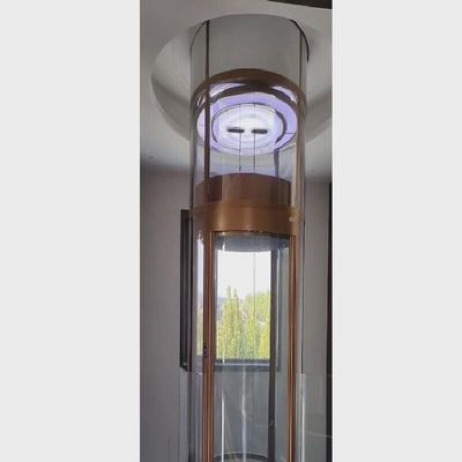
Circular Glass Elevator – 360° Panoramic Cabin for High-Rise Projects
Product Details:
Brand Name
YIMEISITE
Place of Origin
China
Payment & Shipping Terms:
Minimum Order Quantity
1 set
Price
USD 10,000-20,000 per set
Payment Terms
T/T,L/C
Supply Ability
10 sets
Delivery Time
50 working days.
Packaging Details
Export non-fumigation wood box.
| Speed: | 0.6 m/s | Capacity: | 400Kg |
| Travel Height: | 50m | Operating Temperature: | 0-40℃ |
| Control System: | Microprocessor | Door Type: | Automatic |
| Model: | AE-100 | Safety Features: | Emergency Stop Button |
| Number Of Stops: | 15 | Power Supply: | 220V, 50Hz, Single phase |
| Warranty: | 1 Year | Installation: | Professional Installation Required |
| Drive System: | Gearless Traction | ||
| Highlight: | 400Kg Capacity Special Elevator,Special Elevator 15 Stops,15 Stops Small Residential Elevator | ||
Product Description
A circular glass elevator turns the travel path into a visible part of the building. This model is published at 400 kg, up to 15 stops and up to 50 m of travel, with a 0.6 m/s gearless traction drive, microprocessor control, automatic doors and a 360-degree panoramic cabin.
Those figures make the product suitable for consideration in high-rise residential, hotel and selected commercial projects. They do not prove that every circular lobby can take a circular lift. The real decision starts with the travel path: the shaft or fixed enclosure, the measured landing openings, the position reserved for the traction equipment, the electrical supply and the route for service access.
- 400kg published capacity
- 15stops listed
- 50m maximum travel
- 0.6m/s published speed
- 360°panoramic circular cabin
This page uses the product information published for this item. It does not infer certification, clear cabin diameter, shaft diameter, pit depth, headroom, door clear width, passenger count or installation duration from other lifts. Where a value is not published, the approved project drawing and written specification control.
1. Choose the right project for a circular glass elevator
A circular glass lift is often treated as an interior feature first. In a hotel atrium, it can make vertical movement legible from several floors. In a high-rise residential building, it can give a small lobby a clear visual centre. In a commercial building, the glass car may help visitors understand where the lift is going while keeping the travel route open to view.
The product still behaves as a lift. It needs a safe travel path, a controlled landing entrance, a rated load, a drive and control system, a way to isolate power, and access for inspection and service. The circular cabin changes the geometry and appearance. It does not remove those project requirements.
Where the 15-stop, 50 m range is useful
The published 15-stop limit and 50 m travel figure point to a project where the lift serves more than a short residential rise. That may be a tall residential common area, a hotel with several public levels, or a building where the lift remains visible through a central void. Measure every floor-to-floor distance. A nominal 15-storey building may travel less or more than 50 m.
A 15-stop system at long travel needs drawings for guide alignment, landing interfaces, driving geometry, equipment access and the electrical design. The quotation should state which parts are included and which are project-side work.
Projects that fit the product story
- High-rise residential common areas: a feature lift connecting a ground lobby with upper amenity floors, where residents and visitors can see the car and the route.
- Hotels and serviced buildings: a visible passenger route between lobby, restaurant, lounge or meeting levels.
- Design-led commercial buildings: a lift placed within an atrium or entrance hall where the movement itself is part of the interior.
- Custom projects with a defined maintenance model: an owner or operator can support inspection, cleaning, spare parts and service access throughout the life of the equipment.
Projects with unrestricted public access, evacuation duties, fire-service use or a statutory passenger-lift classification need a separate compliance review with the local authority and building designer.
Screen the four conditions that decide the next step
The check below is a planning prompt, not an approval. It looks for the enclosure route, the measured landing entrance, a reserved position for the traction equipment and a compatible electrical supply. If any answer is still open, the correct next action is a measured survey.
Final selection depends on the measured plan, structural review, electrical design and local acceptance requirements.
What a circular picture cannot show
A photograph cannot show the metal frame behind a finish, guide alignment, door clear opening at the finished wall, load path or component replacement route. Those items belong in the technical package.
Two quotations can show similar round cabins and include different scopes. Compare the car, doors, drive, control, enclosure responsibility, electrical work, installation and commissioning line by line. The lift becomes a reliable purchase when the full route is measured and the equipment boundary is written down.
2. The 360-degree circular glass cabin
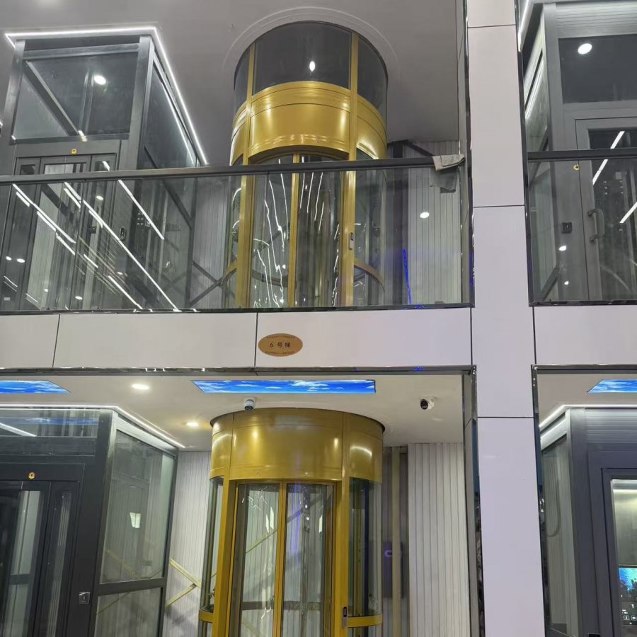
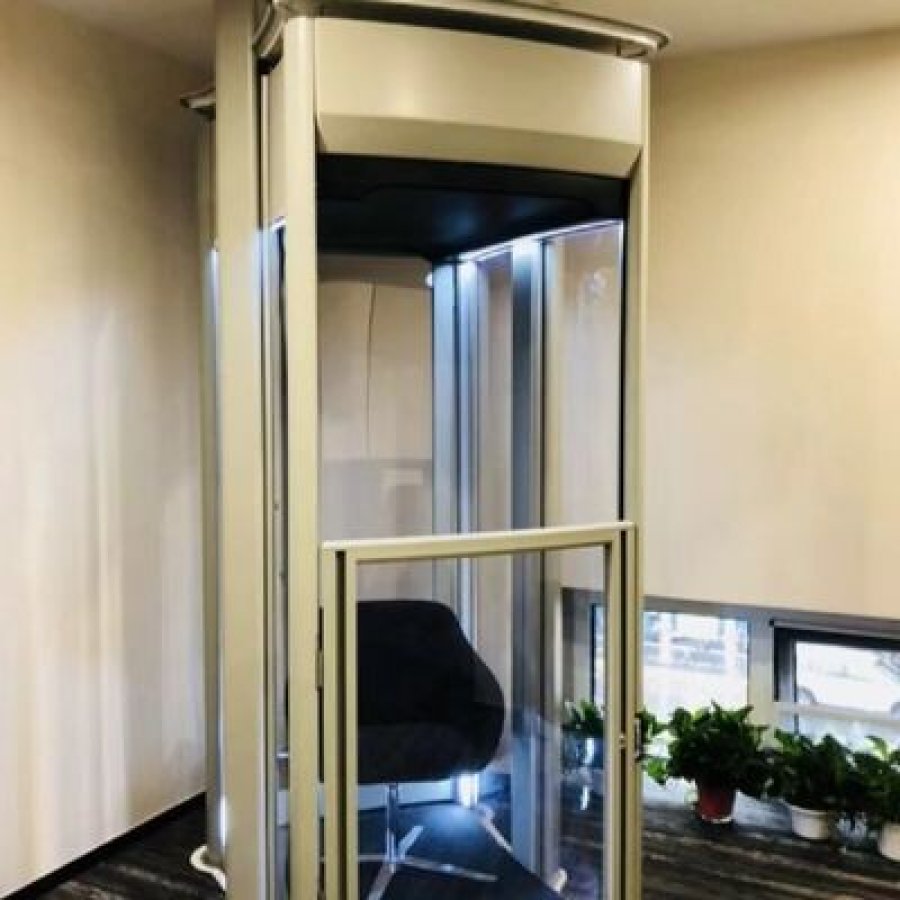
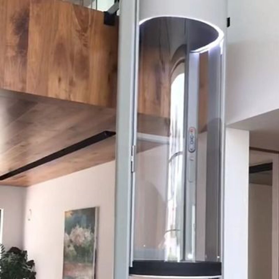
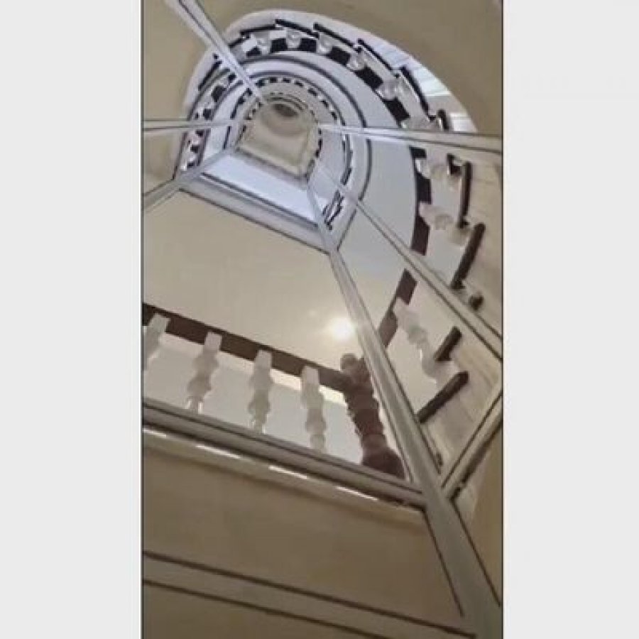
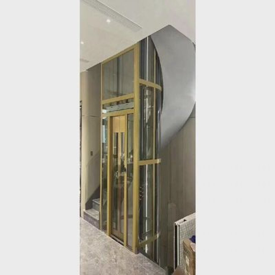
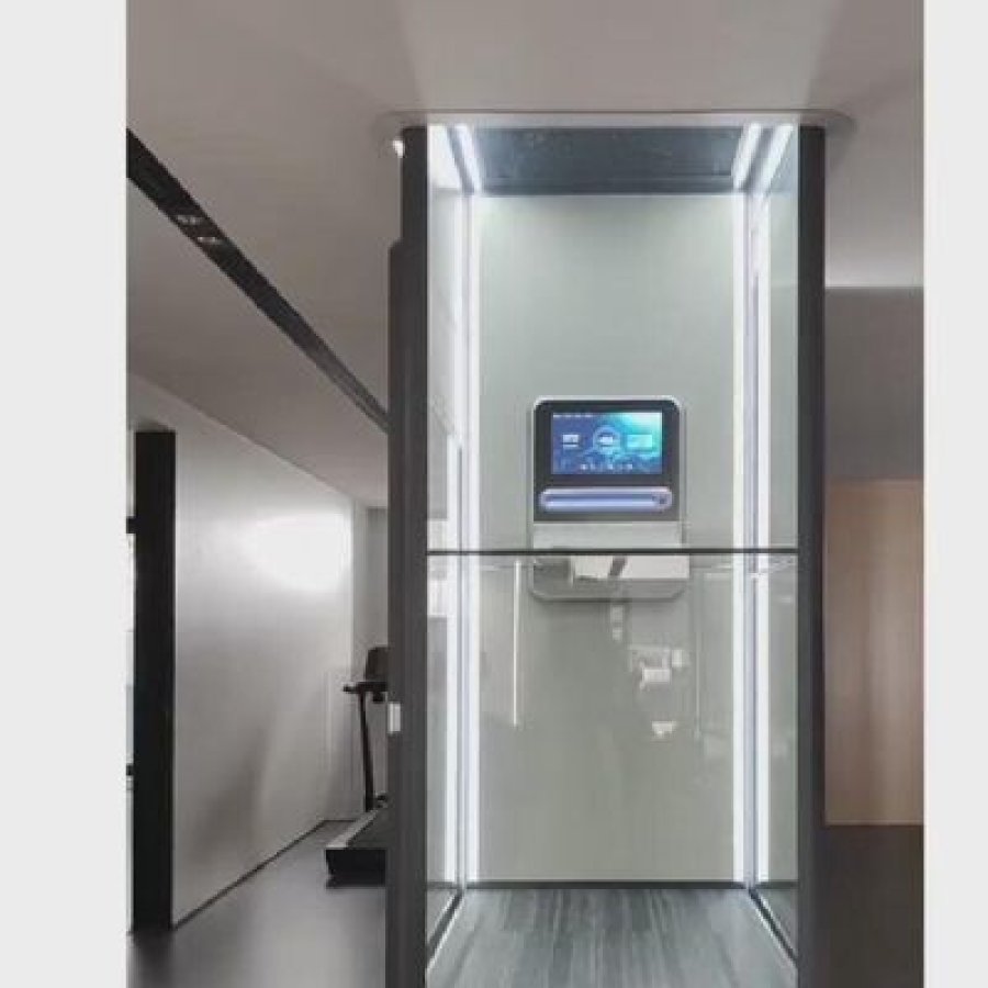
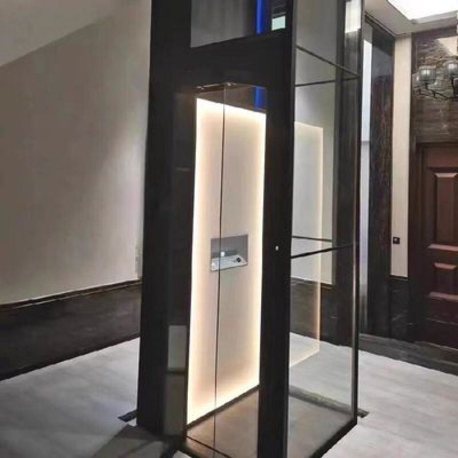
The cabin is the part people remember. In this product, the panoramic circular car places glass around the passenger area and makes the movement between stops visible from inside and outside. That effect depends on more than a transparent panel. Curved glazing, the frame that holds it, the door position, the floor edge, the ceiling, the lighting and the handrail all shape how open the car feels.
The photograph is useful for discussing the architectural character. It cannot be scaled to obtain a cabin diameter, door clear width or shaft size. Those dimensions need a drawing with the finished wall line, glazing position, frame depth, door track and service access marked.
Why a round cabin feels different
A rectangular car presents corners and straight walls. A circular car presents a continuous perimeter and a changing view as the passenger moves inside it. The result can feel more like a viewing room than a conventional lift. The visual openness also means that the travel path is exposed to inspection by everyone in the surrounding space. Frame alignment, door gaps, floor joints and the back of the glazing need to look controlled from more than one direction.
The plan should lock four relationships
- Cabin centre and shaft centre: the approved drawing should show whether the car sits concentrically inside the enclosure or at an offset.
- Door position: the entrance must meet the landing approach and preserve the intended glass arc on the remaining cabin perimeter.
- Frame and joint lines: the visible mullions should follow the fabrication and transport divisions rather than a decorative line that cannot be built.
- Floor and ceiling interfaces: the cabin floor, sill, doors and ceiling details need a common datum so the completed car closes neatly.
Glazing needs a project review, not a generic promise
The current product information identifies a 360-degree panoramic circular glass cabin. It does not publish glass thickness, laminate construction, impact performance, fire performance or acoustic performance. Those properties should not be copied from an unrelated product page. If the project requires a specific glass build-up or documentation, ask for it in the quotation and compare it with the design specification.
The same rule applies to privacy and solar control. Clear glass may suit an atrium where the route is meant to be visible. A west-facing lobby, hotel corridor or residential landing may need a different treatment. Tint, interlayers, patterned film and lighting can change the appearance, but each option must be reviewed for the final cabin design and local requirements.
The cabin should be easy to read from the landing
Passengers need to recognise the entrance, see the floor, cross the threshold and enter without treating the curved wall as a hidden obstacle. A continuous glass perimeter can make the door less obvious. The entrance frame, floor finish, lighting and call controls should establish a clear boarding edge.
Review the cabin and landing drawings together. A door placed after the glass circle is finalised can interrupt the design, while an entrance fixed before the finished floor is checked may create the wrong threshold. The plan, frame and entrance are what make the panoramic idea work as a passenger lift.
3. Published circular glass elevator specifications
The table below keeps the main product figures visible on one screen. Use the unit buttons to compare metric and imperial values. The converter is included for early drawing discussions. It does not approve a site measurement or replace the signed technical schedule.
For circular glass elevator dimensions, use the drawing package. The published load, travel, speed and stop limits do not define the cabin or shaft envelope.
| Specification | Published value | What it controls |
|---|---|---|
| Product | Circular glass elevator | Circular 360-degree panoramic passenger cabin. |
| Model reference | AE-100 | Reference shown with this item; confirm the exact code on the quotation. |
| Capacity | 400 kg881.85 lb | Rated load; passenger count still follows the approved cabin plan and local rules. |
| Maximum stops | 15 | Landing interfaces, control schedule and the service strategy. |
| Maximum travel | 50 m164.04 ft | Vertical route and the arrangement of the gearless traction system. |
| Speed | 0.6 m/s118.11 ft/min | Ride pace and the coordination of acceleration, stopping and door time. |
| Drive | Gearless traction | Traction machine, support point, travel-path clearance and service access. |
| Control | Microprocessor | Car calls, landing calls, position inputs and fault information. |
| Door type | Automatic | Landing entrance, threshold, door clear opening and operating state. |
| Power supply | 220 V, 50 Hz, single phase | Project electrical design, isolation, protection and cable route. |
| Named safety feature | Emergency stop button | One device named on the page; the complete safety schedule belongs in the approved package. |
| Installation | Professional installation required | Who performs the work and how the interfaces are coordinated. |
| Warranty | 1 year | Published commercial term; exclusions and start date should be written into the order. |
Planning converter
Conversions are rounded for discussion. Final values, tolerances and acceptance criteria must appear in the approved drawing and signed technical schedule.
Read capacity and stops as a system
The 400 kg capacity is the published rated load. It is not a statement that every 400 kg of people, luggage or equipment can be arranged in any shape inside the car. The approved cabin drawing determines usable floor area, the door opening and the distribution of load. Passenger counts vary by body size, mobility aids and local rules, so this page does not convert 400 kg into a fixed number of people.
Read travel and speed together
The 50 m travel figure and the 0.6 m/s speed describe the published range and pace. Dividing 50 m by 0.6 m/s gives a simple reference travel time of about 83.3 seconds, but a real trip also includes acceleration, deceleration, door movement and the time needed to confirm a safe landing. The simple division is useful only for comparing the scale of a journey. It is not a promised door-to-door time.
The electrical statement needs project review
This page publishes a 220 V, 50 Hz single-phase supply. It does not publish current, protective-device rating, cable size, isolation arrangement or generator compatibility. Those values should be calculated for the final configuration and confirmed by the project electrical designer.
What the table does not settle
The product information does not state certification, circular cabin diameter, shaft diameter, door clear width, pit depth, headroom, traffic capacity, maintenance interval or installation duration. Those are not gaps to fill with a guess from another model. They should be issued in the project documents or marked as information still required.
The table fixes the public starting point. The buying process is complete when every dimension and responsibility around those figures is written into the quotation, drawing package and handover documents.
4. Gearless traction over a travel height of up to 50 m
The product uses a gearless traction drive. In simple terms, a traction machine creates movement at a rotating element and transfers it to the car through the lifting system. Removing a conventional gear stage can reduce the mechanical train, but the design still depends on correct alignment, support and controlled motion. The product page does not publish the number of ropes, rope ratio, counterweight, sheave size or detailed layout, so those values should not be inferred from the words “gearless traction”.
A maximum travel of 50 m gives the lift a larger working envelope than a short home lift. The longer route raises practical questions. How is the drive alignment maintained from the lowest to the highest landing? Where can the machine be inspected? How does the travel path behave under building movement or temperature change? Who confirms the support loads? These questions belong to the project review.
What the 0.6 m/s figure is good for
The published speed is 0.6 m/s. That is a moderate travel pace, useful for discussing how quickly a passenger moves between floors without treating the figure as the whole journey time. A car cannot reach line speed instantly. The controller has to accelerate, run, approach the landing and stop. Door operation adds more time at each end. For a long route, a clear door and an efficient call strategy can matter as much as a small difference in nominal speed.
Mechanical review belongs before the order
Published
The page states gearless traction, 0.6 m/s, up to 15 stops and up to 50 m travel, with microprocessor control.
These values can be used to frame a technical evaluation.
Required from the project
The final machine position, support point, structural loads, travel measurement, guide arrangement and service route must be shown on the approval drawing.
These are project conditions, not optional sales details.
Required before handover
Commissioning checks should cover alignment, stopping level, door movement, emergency stop and the agreed acceptance items.
The final test schedule should come from the approved package.
Where long-travel schemes fail early
One common failure is to finalise the cabin design before the travel route. A round cabin may receive a door position that conflicts with the machine room or service space. Another is to treat the traction machine as a generic piece of equipment without confirming its support. A third is to leave the electrical route until the shaft is closed.
A gearless traction lift at this scale can be a practical choice when those interfaces are controlled. It should be selected because the route and service model fit, not because the term “gearless” sounds more advanced than another drive.
Questions to put in the technical return
- What exactly is included in the traction equipment boundary?
- Which support loads and fixing conditions must the building satisfy?
- Where are the isolation, inspection and service positions?
- Which landing dimensions must be verified before manufacture?
- What commissioning records will be issued at handover?
- Which components have a spare-part recommendation?
5. Shaft, landing and circular cabin planning
The greatest risk in a circular glass lift project is a design that relies on a beautiful perspective but not a measured plan. The cabin may be circular, yet the finished installation still meets square walls, straight landing openings, structural slabs, finishes, door tracks and service zones. The purpose of the planning drawing is to show how those different geometries meet.
This product page does not publish cabin diameter, shaft diameter, pit depth, overhead clearance or door clear width. No value is estimated here. The correct method is to obtain the approval drawing for the selected arrangement and measure each site condition at the finished face. The drawing should show the lift envelope, the building structure and the clear route to the entrance on the same sheet.
Measure from the finished building
“Finished face” means the surface after tiles, stone, plaster, cladding or other finishes are installed. Measuring only the structural opening can leave too little space for the frame, door, threshold or trim. Each landing should be recorded with the same datum so the survey does not combine an unfinished opening on one floor with a finished opening on another.
Use a consistent vertical datum from the lowest finished landing to the highest. Record every floor-to-floor distance and the total travel. Note whether the structural slab is level and whether a floor build-up will be added later. The final lift drawing should use the same dimensions and identify which party owns each finished surface.
Checklist: the three conditions to settle first
Ready status: 0 / 3 ready
Use the same drawing for architecture and engineering
Architectural plans often show the outer finish. Lift drawings need to show the clear zones, equipment boundary and service access as well. A useful coordination set contains a plan, a section, representative landing details and a schedule of finishes. The plan should identify the door location and the direction of the cabin entrance. The section should show the travel path from the lowest to highest landing and the equipment position.
If a curved glass cabin sits inside a square shaft, the drawing should show the relation between the round car and straight enclosure. If the enclosure follows a circular form, it should show how landing doors and structural supports interrupt the circle. A tile or stone change can also alter the finished threshold, so record the intended floor build-up with the lift drawing.
Questions for the surveyor and designer
- Is every dimension taken from the finished face?
- Do all floors use the same vertical datum?
- Is the landing approach clear of doors, furniture and fixed services?
- Is there a position for the traction equipment with support and maintenance access?
- Can the electrical isolation and cable route be reached safely?
- Will the glass and frame be delivered through a route that exists?
The drawing should answer more than “will the cabin fit?” It should show how the cabin is entered, how the equipment is serviced and how the project will finish the interfaces. That standard is more useful than a single estimated diameter.
6. Power supply, microprocessor control and door operation
The published electrical statement for this model is a 220 V, 50 Hz single-phase supply. The control system is described as microprocessor based and the doors as automatic. Together, those features define the equipment interface, not the complete electrical installation. The final supply, current, isolation, protection, cable route and earth arrangement must be designed for the actual project.
This distinction directly affects a high-rise design. The equipment serves up to 15 stops and up to 50 m of travel, so the electrical route may cross several floors, fire compartments and service zones. The building designer and electrical engineer should confirm the isolation point and maintenance route before manufacture.
Supply named on the page
220 V, 50 Hz, single phase. This is the published equipment value. It is not a project load calculation.
Control named on the page
Microprocessor control. The final control functions, landing call arrangement and fault display should be listed in the technical schedule.
Door type named on the page
Automatic doors. Door clear width, opening direction, sill details and landing coordination still require the drawing.
Project values required
Current, cable, isolation, protection and earth. These values are not published here and must not be guessed from the voltage alone.
What the electrical questionnaire should ask
Ask the project electrical designer to confirm the supply voltage, frequency and number of phases at the planned isolation point. Then add the position of the isolation device, the cable route, the available protection arrangement, the earthing method and the responsibility for final connection. If a generator or UPS will be involved, state that early. A lift may need a defined shutdown or recovery procedure, but the product page does not publish a backup-power function, so it should not be promised.
What microprocessor control can contribute
A microprocessor controller takes input from the car and landing controls, checks position and operating conditions, and coordinates the drive and door sequence. The value for a circular glass lift is that the control system can manage repeated stops while keeping the visible interfaces consistent. It can also report status information, provided the final controller is configured to display it.
The product page does not list remote monitoring, phone diagnostics, destination dispatch, battery lowering or a particular fault-code interface. Those functions should not be added to a quotation by assumption. If the building wants them, specify them as requested options and ask for the exact hardware and protocol.
Automatic doors need a complete landing interface
Automatic doors reduce the manual action at each floor. They still need a clear threshold, a safe landing condition, a correct door clear opening and coordination with the cabin entrance. The survey should measure the finished opening and the approach together. A door can be technically operational yet still be difficult to use if the approach is obstructed or the threshold is not flush with the landing.
Ask who supplies the landing door, who finishes the surrounding wall and who sets the sill. If those scopes are split between the lift supplier, contractor and interior fit-out team, put the interfaces in writing. A circular cabin may be the visual focus, but the landing door is where passengers meet the building.
Terms that should not be confused
- The unobstructed width left after the door, frame, handle and fixed trim are fitted at the finished wall line.
- The vertical distance between the lowest and highest served levels. The page lists a maximum, not a measured project dimension.
- The gearless machine and associated equipment. Its support, position and service access belong to the approved layout.
Review the power and control package as one chain from supply to equipment, doors and cabin. A complete schedule makes the quotation comparable and the installation safer to plan.
7. Safety, landing control and project acceptance
The equipment information for this model names an emergency stop button, automatic doors and professional installation. It does not list the complete safety-device schedule, a certification or a standard number. The page should therefore be read as a starting point for a project-specific safety review. A buyer should not infer any additional device, rating or approval from a photograph or from a similar product.
01 / Emergency stop
The page names an emergency stop button. Its final position, labelling and function should be shown in the equipment schedule and demonstrated at handover.
02 / Automatic doors
Automatic doors control the entrance, but the landing approach, finished threshold and clear opening still need measured details.
03 / Controlled travel
The gearless traction system and microprocessor control must be commissioned together. Stopping level and door sequence should be part of the agreed test record.
04 / Professional installation
The page requires professional installation. Confirm who performs installation, who connects the building supply and who handles the final inspection route.
Landing interface: where people meet the system
A glass cabin can be visible from several floors, which makes every landing state feel connected. That visual relationship should not replace the formal interface. The landing needs a clear approach, a door that operates in the expected direction, a visible state and a safe threshold. Finished car and landing levels should meet without a trip hazard. Door movement should not surprise a passenger near the entrance.
The approved drawing should show the door position at each stop and identify whether the landing wall follows a straight or curved plan. It should also show the space needed for the frame, track and finish. If the building contractor reserves a nominal opening but later adds stone or a deep reveal, the clear opening can change. The survey therefore needs to use the finished face and note the intended finish build-up.
Project checklist before manufacture
Project readiness: 0 / 6 ready
Do not turn a feature list into a certification
“Emergency stop” and “automatic doors” are features. They are not a statement that the complete installation is certified for a particular market. The page does not publish CE, ISO, ASME or other certification, so none is claimed here. If a tender requires a certificate, ask for the exact certificate holder, scope, standard, issue date and validity period. Compare those details with the project requirement.
What should be tested at handover
At handover, confirm that every landing is reachable, the car responds to calls, the doors operate as intended, the emergency stop can be reached and demonstrated, and the operating instructions are available. Record incomplete items with an owner and date.
Collect the drawings, control information, maintenance instructions, warranty terms and inspection records. A coordinated system whose conditions can be inspected and maintained is the goal; leave unlisted equipment out of the acceptance claim.
8. Installation sequence and a printable site survey
Professional installation is a named requirement on this product. That phrase covers a sequence of decisions, not a single delivery event. The lift should be installed against current drawings, with the building interfaces complete and the site access confirmed. The sequence below is a project workflow. It is not a promised duration and does not replace the installer’s method statement.
From measured survey to handover
1. Measure the finished site
Record every landing, the travel route, the enclosure, the landing approach, the electrical supply and the traction-equipment zone. Use finished faces and one vertical datum.
2. Review the approval layout
Check the circular cabin, door position, structure, service route and equipment support together. Resolve clashes before finishes or framing are closed.
3. Freeze the configuration
Put cabin finish, glazing treatment, door arrangement, supply, inclusions, exclusions and acceptance responsibilities into the order documents.
4. Prepare the interfaces
Complete the supporting structure, openings, landing protection, isolation point, cable route and safe storage or lifting plan required by the approved method.
5. Install the lift system
Set the guide route, traction equipment, controller, car, doors and landing interfaces to the current drawing. Protect finishes and maintain the agreed clearances.
6. Commission and hand over
Run the agreed operational checks, record settings, demonstrate the named safety features and issue the drawing, service and warranty information.
Printable ten-point survey
Complete this sheet on site. Attach photographs and the floor plans. Mark every value as measured, planned or still unknown. The print button produces a clean checklist containing the same ten points.
Survey status: 0 / 10 ready
Put responsibility beside each measurement
A survey becomes useful when every dimension has a decision attached. For each opening, note whether it is existing, planned or still to be cut. For each finish, note who supplies it and when it will be complete. For the supply, note who provides the isolation point and who makes the final connection. For the traction equipment, note who confirms the support and who needs access after installation.
Survey before the finishes hide the evidence
Once wall linings, stone and ceiling panels are installed, controlling dimensions become difficult to inspect. Photograph the structure, opening and service path before closure. Mark the datum on each floor. If a later change alters a finished face, update the drawing and send the revision to the lift supplier.
No fixed installation duration is promised here
The product page does not publish an installation duration, and the time depends on the building, access, inspection route and scope. Commercial terms on the page list a delivery time for the product, but delivery is not the same as site completion. Ask the supplier and installer for a project-specific sequence that names the site readiness conditions.
9. Service planning, warranty and long-term access
The published warranty term is one year. The page does not publish a maintenance interval or a list of warranty exclusions. Those details should be obtained in the quotation and order documents. A one-year term is not a complete service plan, and a low equipment price is not a useful comparison if the building cannot reach the machine or replace a component later.
Service planning starts before installation. The circular cabin may be visible and easy to show, but maintenance access usually depends on the less visible route around the travel path and traction equipment. The building owner, installer and supplier should agree who can enter the equipment zone, how the area is isolated and which components need floor or ceiling access.
Published warranty
1 year. Obtain the start date, covered components, exclusions and service conditions in writing.
Maintenance interval
Not published here. The signed maintenance plan should follow the final equipment and local requirements.
Spare parts and lead times
Project-specific. Ask for recommended wear parts and the procedure for identifying replacements.
Service access
Design requirement. The approved layout should keep the equipment, isolation point and inspection route reachable.
Operating checks for the building team
The operating routine should follow the supplier’s instructions. Before passengers use the lift, the landing and car floors should be clear, the doors should move without obstruction and the call controls should be visible. The building team should know how to take the lift out of service and how to contact the responsible service provider. A fault should be reported with the floor, time and observed state rather than reset repeatedly without a record.
Planned service should include the travel path
Routine service should not focus only on the visible car. The travel path, guides, landing interfaces, controller, traction equipment, doors and emergency stop should all be included in the agreed service schedule. For a long installation, alignment and stopping performance deserve observation across the route rather than only at one representative floor.
Ask the service provider to return a record of each visit. Include the date, work performed, measurements where applicable, parts replaced and any item that needs follow-up. A consistent record makes it easier to distinguish normal wear from a repeated fault and supports the warranty discussion.
Spare parts should be identifiable
A service team needs more than a product name to order a part. The order file should contain the model reference, controller information, door arrangement, electrical schedule and approved drawings. Update the file when a finish or control option changes, especially where the cabin has curved glazing or a custom frame section.
Warranty review before signing
- When does the one-year term begin?
- Which equipment and workmanship are covered?
- Which exclusions apply to water, glass, finishes, electrical supply or third-party work?
- Who performs warranty service and within what process?
- Which records must the owner keep?
- Are replacement parts and labour treated the same way?
A clear service file is part of the product value. Visitors notice the glass cabin; service access, isolation and documented responsibilities keep the installation usable after the opening event.
The buyer should request a handover pack containing the approved drawings, operating instructions, maintenance requirements, warranty terms, contact route and inspection records. Store one controlled copy with the building operations team and another with the lift file. When a future service visit begins, the technician should be able to identify the exact configuration without guessing from the cabin shape.
10. Circular glass elevator FAQ
These answers use only the product information published on this page and the limits of that information. They do not turn a project assumption into a product specification. If an answer depends on the building, ask for the approved detail in writing.
Is a circular glass elevator a real passenger lift option?
Yes. This product is a circular glass elevator with a 360-degree panoramic cabin, listed for high-rise residential, hotel and selected commercial use. The approved drawing still has to establish the dimensions, door position, enclosure, support conditions and service access.
How high can this circular glass elevator travel?
The page lists a maximum travel of 50 m and a maximum of 15 stops. Measure the distance between the lowest and highest finished landings. A 15-stop building may travel less or more than 50 m because floor heights vary.
What is the speed of the lift?
The published speed is 0.6 m/s. Dividing 50 m by 0.6 m/s gives about 83.3 seconds at simple line speed, before acceleration, deceleration, door movement and landing confirmation. This is a scale comparison, not a promised journey time.
How much can the cabin carry?
The rated capacity is 400 kg. The page does not give a fixed passenger count, and the answer should not be calculated from body weight alone. Usable floor area, door clear opening, mobility aids, luggage and local rules all matter. Ask the supplier to confirm the permitted passenger loading for the approved cabin arrangement.
What diameter or shaft size does it need?
The current page does not publish cabin diameter, shaft diameter, pit depth, headroom or door clear width. Obtain them from the drawing for the selected arrangement. Do not scale the photograph or copy a value from another model.
Can a round glass elevator be used in a residential building?
A round glass elevator residential project can use this product when the building, public access, landing arrangement and local acceptance route suit the installation. The page identifies high-rise residential as an application. The measured shaft, door and service conditions still decide the final scheme.
Can it run on a 220 V single-phase supply?
The product page lists 220 V, 50 Hz, single phase. Current, cable size, protection and isolation are not published and must be calculated for the final configuration. If the site supply differs, send its voltage, frequency and phase arrangement for review.
Is the product certified?
No certification is stated on the product information used for this page, so none is claimed. If a certificate is required, ask for the holder, scope, standard, issue date and validity period.
What warranty is included?
The published warranty is one year. The starting date, covered components, exclusions, service responsibilities and spare-parts treatment should be written into the order. The page does not publish a maintenance interval, so the service plan must be agreed separately for the project.
What should a buyer send for a circular glass elevator quotation?
Send the finished floor levels, travel, stop count, landing plans, enclosure status, traction-equipment position, supply details and required scope. Ask for the product drawing, inclusions, exclusions and acceptance documents. Contact our engineers if a value is unknown.
Questions that deserve a drawing, not a quick estimate
Where does the traction equipment sit? Which landing door is in each plan? What is the clear opening at the finished wall? Where is the isolation point? How will the glass reach the installation position? Send the drawing set with these questions and mark every unknown value. If a product figure and a project drawing differ, record the conflict and obtain a written response.
11. Build a quotation request for your circular glass elevator
A useful enquiry gives the supplier enough information to price the complete travel route. Start with the building plan, the floors served, the intended use and the desired visual direction. Then add the conditions that decide the design: enclosure, landing approach, traction equipment, power route, delivery and who will install the lift.
Quotation request checklist
Quotation pack: 0 / 10 ready
What to send first
Send a plan at each floor, a section through the travel route and photographs of every landing. Mark the intended door position on the plan and the likely traction-equipment location on the section. If the design is still preliminary, label the dimensions as preliminary and identify every value that is not measured.
Include the finished floor-to-floor heights, the finished landing openings and the available electrical supply. Add the delivery city and the contact responsible for the site survey. For a high-rise project, show how the equipment and glass will reach the installation level and how a replacement component could be removed later.
What to ask the supplier to return
- A dimensioned plan and section for the selected circular cabin arrangement.
- The clear cabin area, landing opening and enclosure envelope, issued as drawing values.
- The final location and support conditions for the gearless traction equipment.
- The electrical schedule, isolation point and connection boundary.
- The landing door, installation, testing and commissioning responsibilities.
- The warranty terms, maintenance information and recommended spare parts.
- A list of every item marked “by others”.
These items make the quote reviewable. If a supplier replies with only a price and a cabin picture, ask for the missing interfaces. A circular glass elevator supplier should be able to distinguish product data from project data and explain which measured conditions are still required.
Buyers comparing circular glass elevator manufacturers should use the same drawing revision, scope and warranty checklist for every offer.
A practical comparison method
Place the offers beside each other under the same headings: capacity, stops, travel, speed, drive, control, doors, supply, enclosure, landing scope, traction equipment, installation, acceptance, delivery and warranty. Mark any difference that changes the building work. Then compare the complete scope beyond the equipment line.
Project summary
This circular glass elevator is published with a 400 kg capacity, up to 15 stops, up to 50 m travel and 0.6 m/s speed. The drive is gearless traction. Control is microprocessor based, the doors are automatic and the listed supply is 220 V, 50 Hz single phase. The page also names an emergency stop button, professional installation and a one-year warranty.
Its 360-degree panoramic cabin is intended for high-rise residential, hotel and selected commercial applications.
The next decision is not whether the round cabin looks distinctive. It is whether the measured route, landing doors, traction equipment, electrical supply and service access can be coordinated into one installation. Once those items are clear, the quotation can be compared on equal technical and commercial terms.
Send your circular glass elevator project details for a configuration review. Missing dimensions will be returned as questions, not replaced with assumed values.
Compare with related glass and panoramic lifts
If a full circular car is not required, compare the capsule lift selection, the glass screw-drive home elevator and the hydraulic panoramic lift for villas on published data, not photographs alone.
Planning a circular glass elevator?
Send the measured route, landing openings, equipment position and electrical supply.
Request a project reviewWant to Know more details about this product
Similar Products